Characteristics of a Sinusoidal Ac Waveform
Web Delivers true rms or average rectified value of ac waveform Fast settling at all input levels Accuracy. What does BS 76712018 require.
Characteristics Of Sinusoidal Signals Sine Waves Video Tutorial
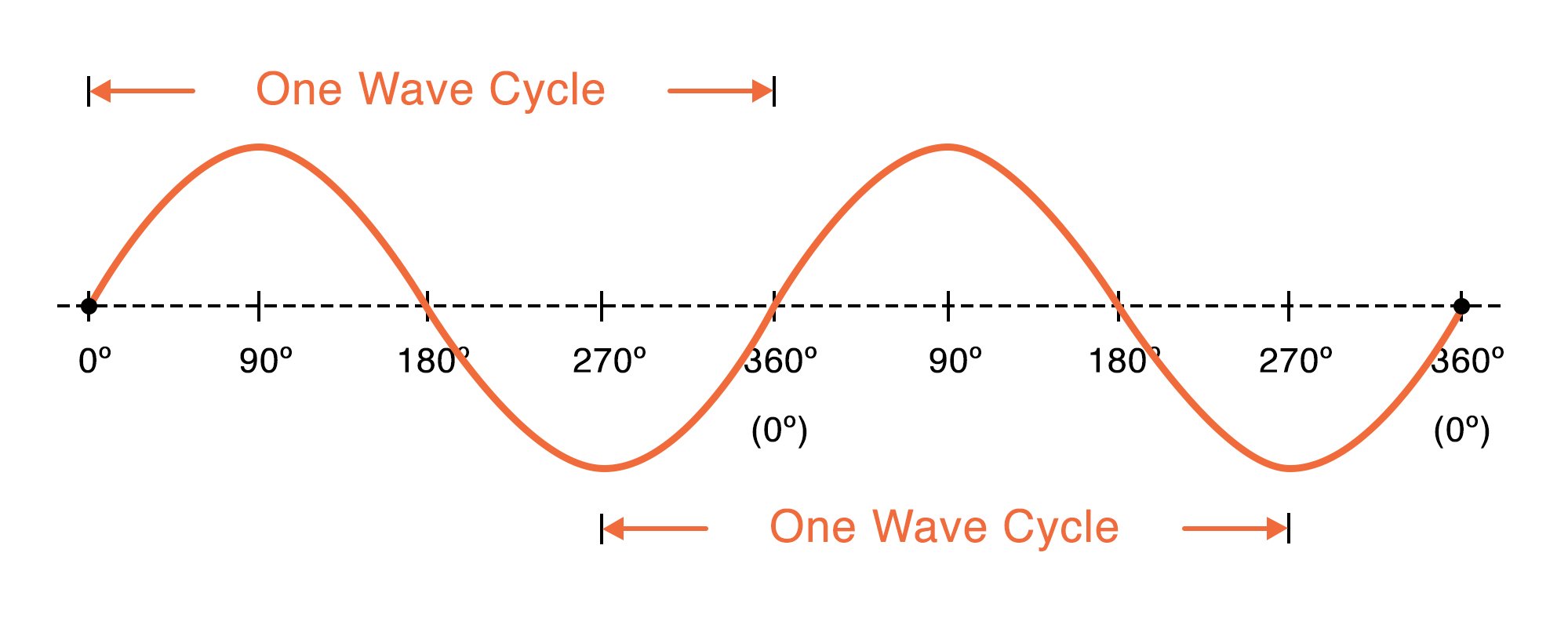
Web A sine wave sinusoidal wave or just sinusoid is a mathematical curve defined in terms of the sine trigonometric function of which it is the graphIt is a type of continuous wave and also a smooth periodic functionIt occurs often in mathematics as well as in physics engineering signal processing and many other fields.
. Web For sinusoidal modelling choose the Sinusoid option and select the number of Harmonics or overtones that you want to add to the fundamental frequency. Web This demonstrates how the shape of the waveform is affected on various types of circuits under load and fault conditions. 100R to 1kΩ and a capacitor value of between.
Active Real or True Power is measured in watts W and is the power drawn by the electrical resistance of a system doing useful work. That is the phase belts overlap. For our example we will put T 2π and fx I m Sinωt in the formula.
Edge slots may contain windings from two phases. Apparent Power is measured in volt-amperes VA and is the voltage on an AC system multiplied. The stray-loss factor for copper conductors varies as the square of the load current and the square of the frequency and will therefore vary with the harmonic mix in the power supply.
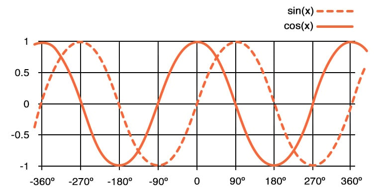
Web We have also seen in our tutorial about series RLC circuits that two or more sinusoidal signals can be combined using phasors providing that they have the same frequency supply. The time period T of the waveform is 2π as evident from its waveform. As a consequence the fundamental component of the voltage has greater.
An op-amp detector that has the ability to detect the change from positive to negative or negative to a positive level of a sinusoidal waveform is known as a zero crossing detectorMore specifically we can say that it detects the zero crossing of the applied ac signal. 10 μV 025 of reading B grade Wide dynamic input range 100 μV rms to 3 V rms 85 V p-p full-scale input range Larger inputs with external scaling Wide bandwidth. Determine the time period T of waveform.
This also leads to alternation in the voltage level as it switches along. With Custom 1 entry per volume you specify a single value for each timepoint. 1nF to 1000uFThis would give a frequency range of between 1Hz to 1MHz high frequencies produce waveform distortion.
Web An AC-AC converter with approximately sinusoidal input currents and bidirectional power flow can be realized by coupling a pulse-width modulation PWM rectifier and a PWM inverter to the DC-link. Web The power factor of an AC electric power system is defined as the ratio active true or real power to apparent power where. In DC circuits the voltages and currents are constant and do not vary with time as there is no sinusoidal waveform function related to the supply.
This is shown in the synchronous motor section. The custom file should. After modulation a PAM signal is generated that is shown in c.
Web The major difference between the AC and DC which is also the cause of their different characteristics is the direction of flow of electric energy. Generally standard TTL logic gates do not work too well as waveform generators due to their average input and output characteristics. Recently introduced in the BS 76712018 Regulation 53133 states that different types of RCD exist and the appropriate type shall be selected according to the connected equipment.
Web The distributed coils of the phase belt cancel some of the odd harmonics producing a more sinusoidal magnetic field distribution across the pole. This PAM signal when added with ramp signal shown in d is compared with the reference voltage of the comparator shown in figure e. Web Here the first image ie a shows the waveform of the sinusoidal modulating signal and the second one b shows the pulsed carrier.
1 MHz for 3 dB 300 mV 65 kHz for additional 1 error. In DC Electrons flow steadily in a single direction or forward while in AC electrons alternate their direction of flow in periodic intervals. In contrast the instantaneous values of the current voltage and resulted power in an AC circuit are continually changing by the supply.
Web The sinusoidal PWM with third harmonic injection THSPWM is a type of sinusoidal pulse width modulation where a harmonic component is added to the voltage signal so that the waveform of the modulating signal has its top flattened and one reduces the period of over modulation. But what would happen to the characteristics of the circuit if a supply voltage of fixed amplitude but of different frequencies was applied to the circuit. Therefore we are not.
The DC-link quantity is then impressed by an energy storage element that is common to both stages which is a capacitor C for the voltage DC-link or an. It is basically a voltage comparator whose output changes when the. Web Electrical Power in an AC Circuit.
The slots at the edge of the pole may have fewer turns than the other slots. RMS Value of sinusoidal AC current is calculated as below. For a single-event experiment with irregular timing for the stimulations a custom file can be used.
Although the percentage contribution to distortion by higher harmonics decreases as the harmonic frequency rises its heating effect even if. Web With a resistor value between.
Characteristics Of Sinusoidal Signals Sine Waves Video Tutorial

Ac Power Calculation Ac Power Calculation Formula Power Supply Design Power Efficiency Ac Power

A Sinusoidal Sound Wave Showing Characteristics Of Wavelength The Download Scientific Diagram

Ac Waveform And Ac Circuit Theory Of Sinusoids
No comments for "Characteristics of a Sinusoidal Ac Waveform"
Post a Comment